How to repair a damaged circuit board in a Crane Controller?
 Language
 Français
 Español
 Árabe
Árabe
 Deutsch
 简体中文
简体中文
 Português
 Русский
 日本語
日本語
 한국어
한국어
 हिंदी
हिंदी
 Prancis
 Türkçe
 Tiếng Việt
 Italiano
 ไทย
ไทย
-
Tel
+86 15275228746
-
WhatsApp/WeChat
8615275228746
Blog
Company intro
10000m 2+ Cover Area QINGDAO TOP RUN INTERNATIONAL TRADE CO., LTD Qingdao Top Run International Trade Co., Ltd. has been a professional and leading supplier of construction machinery spare parts in China for over 15 years. With extensive experience and expertise, we have established strong partnerships with top manufacturers to offer a wide range of genuine and OEM parts for brands such as XCMG, SANY, ZOOMLION, SHANTUI, LIUGONG, and more. 80+ Employees View more Looking for properate products? Contact us
Send Message
How to repair a damaged circuit board in a Crane Controller?
Dec 1, 2025
View: 143
As a supplier of crane controllers, I often encounter customers facing issues with damaged circuit boards in their crane controllers. A damaged circuit board can disrupt the normal operation of the crane, leading to inefficiencies and potential safety hazards. In this blog, I'll share some practical steps on how to repair a damaged circuit board in a crane controller.
Step 1: Initial Inspection
The first step in repairing a damaged circuit board is a thorough visual inspection. Use a magnifying glass if necessary to look for obvious signs of damage such as burnt components, cracked traces, or loose connections. Pay close attention to areas around high - power components as they are more prone to overheating and damage.
Check for any physical damage to the board itself, like warping or breakage. Sometimes, a simple impact or vibration can cause a circuit board to crack, which can disrupt the electrical flow. If you notice any loose components, they may need to be re - soldered or replaced.
Step 2: Diagnostic Testing
Once the visual inspection is complete, it's time for diagnostic testing. You'll need a multimeter to measure voltage, resistance, and continuity. Start by checking the power supply pins on the circuit board. Make sure the correct voltage is being supplied to the board. Incorrect voltage can cause components to malfunction or even burn out.
Test the continuity of the traces on the board. A break in a trace can prevent the proper flow of electricity between components. Use the multimeter to check for open circuits by placing the probes at either end of the trace. If there is no continuity, you'll need to repair or replace the damaged trace.
Check the individual components on the board. For example, test resistors to ensure they have the correct resistance value. Capacitors can be checked for proper capacitance and leakage. Transistors and integrated circuits (ICs) may require more advanced testing methods, such as using an oscilloscope to analyze their signals.
Step 3: Component Replacement
If you've identified a faulty component during the diagnostic testing, the next step is to replace it. First, you need to desolder the damaged component. Use a soldering iron and a desoldering pump or wick to remove the old solder. Be careful not to overheat the surrounding components or damage the circuit board traces.
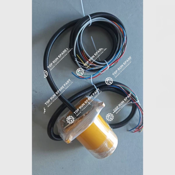
Once the damaged component is removed, clean the area where it was located. This will ensure a good connection when you install the new component. Select a replacement component that matches the specifications of the original one. You can source these components from reliable suppliers. For example, if you need a slip ring for your crane controller, you can find the Slip Ring 60209845 on our website.
Solder the new component into place. Make sure the connections are secure and there are no solder bridges between adjacent pins. After soldering, re - test the component to ensure it is functioning correctly.
Step 4: Trace Repair
If you've found a broken trace on the circuit board, you'll need to repair it. One way to do this is by using a conductive pen. First, clean the area around the broken trace to remove any debris or oxidation. Then, carefully apply the conductive ink along the path of the broken trace. Allow the ink to dry completely before testing the circuit.
Another method is to use a thin copper wire. Solder one end of the wire to one side of the broken trace and the other end to the other side. Make sure the wire is securely soldered and does not interfere with other components on the board.
Step 5: Final Testing
After all the repairs have been made, it's time for final testing. Re - connect the circuit board to the crane controller and power it on. Check all the functions of the crane controller to ensure they are working properly. Monitor the board for any signs of overheating or abnormal behavior.
Use diagnostic tools to verify that all components are operating within their normal parameters. If everything checks out, the circuit board is successfully repaired.
Safety Precautions
When working on a damaged circuit board in a crane controller, safety should be your top priority. Always wear appropriate safety gear, such as safety glasses and anti - static gloves. Anti - static gloves prevent static electricity from damaging sensitive electronic components.
Before starting any work, make sure the crane controller is powered off and disconnected from the power source. This will prevent electrical shock and damage to the equipment.
Conclusion
Repairing a damaged circuit board in a crane controller requires a combination of careful inspection, diagnostic testing, component replacement, and trace repair. By following these steps and taking the necessary safety precautions, you can effectively repair a damaged circuit board and get your crane controller back up and running.
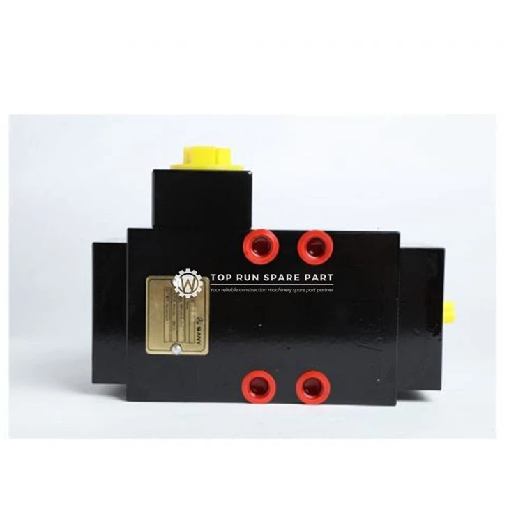
If you're facing difficulties in repairing your crane controller circuit board or need high - quality spare parts like the Hydraulic Gear Pump 60004298 or Balance Valve 60066198, don't hesitate to contact us. We are here to provide you with professional advice and reliable spare parts to keep your cranes operating smoothly. Whether you need further assistance with repairs or are interested in purchasing spare parts for your crane controller, we welcome you to reach out for a detailed discussion and potential business cooperation.
References
- Electronics Repair Manuals
- Crane Controller Manufacturer's Technical Documentation
- Electrical Engineering Textbooks
Categories
QR Code


